ABSTRACT:
Automatic DIM and DIP technology for vehicle headlights has become increasingly popular in recent years due to its potential to improve road safety and reduce driver fatigue. This white paper proposes a new approach to implementing Automatic headlight DIM and DIP using radar sensors. Radar sensors provide real-time information about the distance and speed of the oncoming vehicles enabling the vehicle to adjust the headlights’ intensity and direction accurately. When the sensor detects an oncoming vehicle, the system automatically dims the headlights to prevent glare to the other driver. Similarly, when there is no oncoming vehicles, the headlights return to their normal high-intensity level. The radar sensor used has high accuracy and reliability to measure the distance, speed, and direction of other vehicles. This system uses a sophisticated algorithm to analyze the radar data and adjust the headlights’ intensity and direction accordingly. Automatic headlight DIM and DIP system provides a comfortable and safe driving experience for the driver and other road users.
INTRODUCTION:
Headlights are crucial safety features in vehicles, and their proper functioning is crucial to ensure safe driving, especially at night. However, high-intensity beams can cause discomfort and potentially dangerous glares to other drivers. Auto matic DIM and DIP technology have emerged to address this issue, which enables the headlights to adjust their direction and intensity based on the vehicle’s position in relation to other road users.
This system allows headlights to adjust their direction and intensity based on the position of other vehicles on the road, thereby providing optimal illumination without causing glare to other drivers. Currently available technology for Automatic DIM and DIP typically uses a camera or light sensor to detect the presence of other vehicles or objects in the vehicle’s path. However, these systems have some limitations that affect their accuracy and reliability in certain situations. For example, camera-based systems may struggle in adverse weather conditions such as heavy rain, fog, or snow, leading to false positives or inaccurate adjustments. Similarly, these systems may have difficulty detecting vehicles in high traffic situations, causing them to misjudge the distance or direction of other vehicles.
To overcome these limitations, we propose a new approach to implementing Automatic DIM and DIP technology using ADAS technology through radar sensors. This approach has the potential to significantly improve road safety and reduce the risk of accidents caused by glare or insufficient illumination.
Radar technology overview:
The following radar sensor’s specifications play a crucial role in determining its ability to detect other vehicles on the road accurately and adjust the headlights’ intensity and direction accordingly.
Operating Frequency: The operating frequency of the radar sensor refers to the frequency of the electromagnetic waves emitted by the sensor to detect other vehicles. The frequency range for most radar sensors used in ADAS applications is between 24GHz to 77GHz. The higher the frequency, the more accurate the detection, but at the same time, the more complex the radar system becomes.
Measurable Distance: The measurable distance of a radar sensor refers to the maximum distance at which the sensor can detect other vehicles accurately. For ADAS applications, the measurable distance of radar sensors typically ranges between 20m to 200m. However, the distance may vary depending on factors such as weather conditions and the size and shape of the objects being detected.
Field of View: The field of view of a radar sensor refers to the area within which the sensor can detect other vehicles. For ADAS applications, the radar sensor’s field of view typically ranges between 60 degrees to 180 degrees. The wider the field of view, the more vehicles the sensor can detect, but at the same time, the more complex the radar system becomes.
Accuracy: The accuracy of a radar sensor refers to its ability to detect other vehicles’ position and velocity accurately. For ADAS applications, the radar sensor’s accuracy is typically within a few centimeters and a few kilometers per hour.
Resolution: The resolution of a radar sensor refers to its ability to distinguish between two objects located closely together. For ADAS applications, the radar sensor’s resolution typically ranges between a few centimeters to a few meters.
Distance and speed calculation using radar:
The process of calculating the distance and speed of oncoming vehicles using a radar sensor, one common approach for determining the distance to an object using a radar sensor is to measure the time delay between the transmission of a signal and the reception of the reflected signal. This time delay, also known as the time of flight, is directly proportional to the distance to the object.
The equation for calculating the distance to an object using time-of-flight measurements is:
distance = (speed of light x time of flight) / 2
where the speed of light is a constant value of approximately 299,792,458 meters per second.
To calculate the speed of an oncoming vehicle, the radar sensor uses a technique called Doppler radar. This technique measures the change in frequency between the transmitted and received signals, which is caused by the relative motion between the sensor and the object.
The Doppler shift can be used to calculate the speed of the object using the following equation:
speed = (change in frequency x speed of light) / (2 x transmitted frequency x cosine of the angle between the sensor and the object)
where the transmitted frequency is the frequency of the radio waves emitted by the radar sensor, and the angle between the sensor and the object is the angle between the direction of motion of the object and the direction of the radar sensor.
Using these equations, the radar sensor can determine the distance and speed of oncoming vehicles, which can then be used to adjust the intensity and direction of the vehicle’s headlights to avoid dazzling the driver of the oncoming vehicle while maintaining optimal visibility for the driver of the vehicle equipped with the system.
Working Principle:
The proposed system consists of three main components: the radar sensor, the ADAS, and the headlights. The radar sensor continuously scans the vehicle’s surrounding environment, collecting data on the position and speed of other road users. The data is then sent to the ADAS, which processes the information and determines the optimal headlights’ adjustment. The system then sends signals to the headlights to adjust their intensity and direction to provide the best visibility without causing glare. The headlights will automatically adjust back to their original position once the oncoming vehicle or obstacle has passed. Radar sensors can detect the presence and location of oncoming vehicles by detecting the reflected signals from the vehicles. When a radar sensor emits a signal, it sends out a pulse of radio waves that travels outwards from the sensor. When the radio waves encounter an object, such as an oncoming vehicle, some of the energy is reflected towards the radar sensor.
The radar sensor then receives the reflected signals and uses the time delay between the emitted signal and the reflected signal to calculate the distance to the object. By measuring the Doppler shift of the reflected signals, the radar sensor can also determine the speed of the oncoming vehicle. Using this information, the radar sensor can determine the location and distance of oncoming vehicles, including the position of their headlights. This allows the Automatic DIM and DIP system to adjust the intensity and direction of the vehicle’s headlights to avoid dazzling the driver of the oncoming vehicle while maintaining optimal visibility for the driver of the vehicle equipped with the system. In addition, radar sensors can also detect the size and shape of oncoming vehicles, which can be used to adjust the headlights accordingly. For example, if a large vehicle is approaching, the headlights can be adjusted to avoid dazzling the driver of the oncoming vehicle.
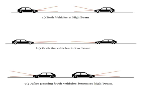
Figure1: Working principle
Benefits of the System:
Conclusion and Future work:
To summarize, the automatic DIM and DIP of Headlight using Radar Sensor is a promising technology that can enhance road safety and driver comfort. However, there are still some challenges that need to be addressed. One of the main challenges is the cost of the technology, which may limit its adoption by some drivers or vehicle manufacturers. Additionally, the system’s performance may be affected by adverse weather conditions, such as heavy rain, fog, or snow, which can impair the radar sensor’s accuracy. Another important aspect to consider is the types of false positive errors that can occur with this technology. False positive errors occur when the system detects an object or obstacle that is not actually present, such as a road sign or a stationary object. These errors can lead to unnecessary adjustments of the headlights, which may cause distraction or discomfort to the driver. These can be pursued as future research directions for this system.