Mobility has always been an important aspect of life. After enjoying every bit of smart mobility experience such as utmost safety, comfort, luxury and functionalities, the conscious community is shifting their focus towards a more sustainable and eco-friendly mobility options which paved the way for an electrified revolution. This shift is largely the result of advanced research on the negative impact of fossil fuels on the environment. Today automakers across the globe promote EVs as one of the clean and green transportation option to curb oil use and battle climate change.
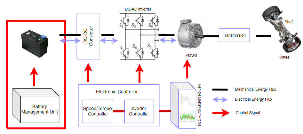
Whether it is an Electric vehicle, hybrid or plug in, the electrified powertrain poses a new set of challenges and opportunities for the industry. The primary part of an electric vehicle system collectively referred to as the “e-Powertrain” or “Electric powertrain system” encompass high voltage batteries, a DC/DC converter, an inverter, an electrical motor, and a supervisory control system. Pure battery Electric Vehicles (EVs) utilise batteries to power the car, but hybrids use fuel cells or gasoline-based ICE to move along. Pure EVs or BEVs have zero atmospheric emissions and represent a means of eco-friendly personal transportation.
Electric Drive Train
The energy storage consists of an Electro-chemical battery. Electricity is exchanged between the battery and the electric motor via the Power Electronics Box (PEB), which regulates and modifies it (EM). The electric motor can transmit power in both directions and transforms electrical energy into mechanical energy. This enables the recovery of kinetic energy from the vehicle during braking and deceleration through process regeneration.
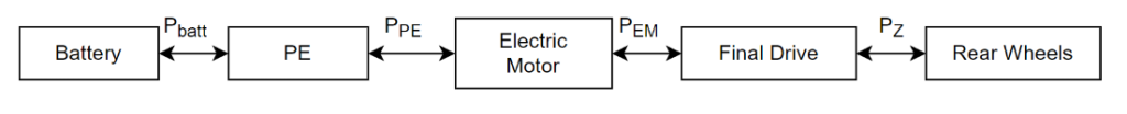
Fig. 1.0. Block diagram of the full electric drive train.
Hybrid Electric DriveTrains
Series hybrid
The most used hybrid powertrain configuration is the series hybrid drive train. In this topology the main torque generator is an electric motor. The electrical generator that powers this equipment is propelled by an engine.
The ideal operating point for this engine is a constant speed. Additionally, a short-term electric energy storage system made of ultracapacitors manages variations in power demand. Based on the hybrid vehicles’ requirements and the overall electric motor power output, ultracapacitors will be chosen. The drive train block diagram given in Fig 2.0.
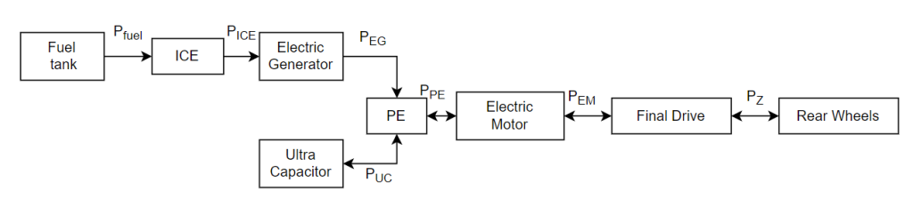
Fig. 2.0. Block diagram of the series hybrid drive train.
Parallel hybrid Electric trains
Parallel hybrids have two power drives: one is Fuel based and another is Electric motor. Each power drive can deliver torque individually or both power drive can be combined to increase output torque. Its key difference from series hybrid Electric train is its ability to deliver output torque to wheels from both fuel power and electric motor simultaneously. The first half of the configuration contain ICE drive train, along a parallel branch of electric drive system.
An electric motor, a PEB, and a collection of ultracapacitors make up the lower part of the powertrain. In some drive trains, power batteries composed of lithium-ion cells are used to replace ultracapacitors. During accelerations and rapid regeneration surges, the ultracapacitors are employed as an additional energy storage source. Additionally supplying torque to the vehicle, the electric machine works.
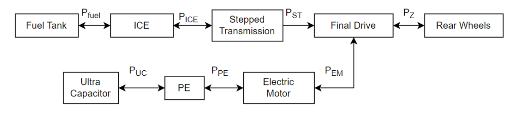
Fig. 3.0. Block diagram of the series hybrid drive train.
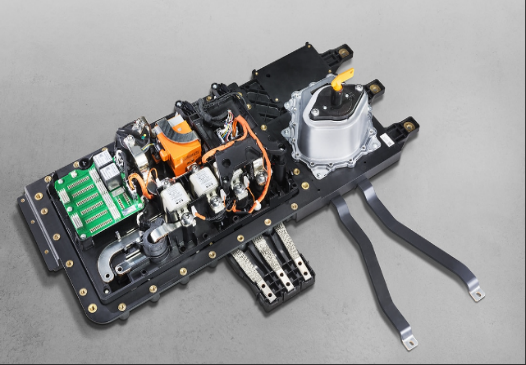
High Performance Higher Power Density Traction Inverter Technology
When a motor needs to be driven or the battery needs to be recharged, traction inverters use sophisticated pulse width modulation (PWM) control techniques to transform direct current (DC) electric power stored in a high voltage battery into three phase alternating current (AC) electric power.
Traction inverters require high-performance control system technology that offers features like direct torque control (DTC), field-oriented control (FOC), and energy regeneration control enabled by communication with vehicle controllers, while enabling features like rotor temperature detection, failure diagnosis, and the functional safety measures specified in ISO 26262.
High Power Density and High-voltage Main Circuit
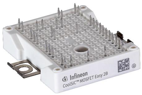
Most of the volume of inverters for HEVs and EVs with standard 450 Vdc- 800 Vdc class batteries come from the high-voltage main circuit, so improving main power circuit component parts is the key to reducing inverter size. Wide-bandgap (WBG) power semiconductors, such silicon carbide (SiC) and gallium nitride (GaN), have recently been utilised for new generation inverters. Both these semiconductors can sustain higher frequencies, higher voltages, and more compact design electronics than silicon semiconductor devices.
Next-generation Lithium-ion Battery Packs
Lithium-ion has the highest energy density & feasible among other commonly used cell technologies. In new generation vehicles Lithium-ion batteries power density has increased recently. New cell chemistry has overcome challenges in early general cells. These technologies have reduced heat generation and thermal management and cooling requirements by thermal friendly materials. Advancements in cell chemistry & cell design in improved battery packaging and enables a compact design further to improve the power density improvement and enables better torque characteristics during motor acceleration.
Solid state batteries are new technology developments happening in Energy storage systems. It promises greater energy storage density, increased reliability and wear resistance, improved operational safety. At high temperatures, liquid electrolytes become volatile and flammable. The risk of fire or explosion is reduced by strong thermal stability of solid electrolytes, on the other hand. Comparing them to other cell chemistries, solid-state batteries are smaller and more energy dense per unit of area. When comparing two batteries of equal size, a solid-state battery’s energy density can be up to 10 times higher.
Advanced EV Motor Control Techniques
The traction motor is the main component of electric vehicles, hence it is critical to improve EV traction control methods. The electronic component consists of an automotive-grade microcontroller and a set of algorithms that allow the motor to operate as efficiently as possible. The commonly applied control techniques are direct torque control and indirect field-oriented control. Various modifications have been made to conventional techniques to improve the efficiency and performance specifications.
Cost reduction has always been a factor in motor control applications as the number of components like optical encoders, Hall effect sensors, and current sensing transformers required to determine speed and position is high. Hence, sensor-less motor control has proven to be a superior solution than traditional and costly sensor-based techniques.
Intelligent Battery Management System
Battery Management Systems (BMS) provide the foundation for making battery activity more effective for evaluation to keep the battery condition viable, avoid damage, and extend battery life cycle. Intelligent BMS is primarily concerned with traction battery functioning and protects it from overcharging, over discharging, and excessive current while charging and discharging. Thermal control of battery packs influences battery safety and usable life, which is also supplied by BMS. It protects both user and battery by confirming the operation of the cell within its safe operating parameters, monitoring the State of Charge (SoC), State of Health (SOH), and State of Power (SoP) of the battery. BMSs are getting simpler with fewer wires, safer with more accuracy and data granularity, and electrically insulated from high voltage domains.
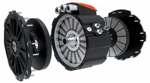
Axial Flux Electric Motors for EV Powertrain
Axial Flux motors are gaining popularity in the e-mobility market recently. Axial flux motors can modify the way a powertrain is constructed by relocating it from the axle to the wheel. These permanent magnet machines provide more torque for a given volume of motor than conventional motor as the active magnetic surface area is the face of the motor. The axial length of these machines is much shorter than the radial flux machines and the motor is two to five times lighter making it more compact and suitable for crucial applications changing the options for EV platform designer. Axial flux motors are classified into two topologies: dual-rotor single-stator (also known as torus type machines) and single-rotor dual-stator. The e-axle was one of the first axial motor uses. Because of the narrower width, the engine and gearbox may be housed within the axle. The motor’s small axial length keeps the total length of the drivetrain modest in hybrid applications.
New Generation modelling and simulation software for electric powertrain system
An electric motor, a battery with a battery management system (BMS), a DC-DC converter and traction inverter, and a vehicle controller module comprise the electrical modules (VCM). The mechanical system includes a transmission system, an axle shaft, and wheels. The vehicle speed, engine torque and speed, and battery state of charge SOC are monitored on a real time basis.
Simulation approach determines the most optimal traction drive parameters in ePowertrain and refine the traction inverter and traction motor performance. Circuit level modelling and simulations are independent of the vehicle system and powertrain system. Objective of circuit level simulation is to optimize power electronics systems or traction inverter in ePowertrain for its performance and dynamic responses.
Motor control algorithm and traction control strategy.
During powertrain operation large variants of dynamics is imposed on electric motors. Magnetic and electric fields analysis and current control at higher precision is key to motor control techniques. To enable efficient control of electric motor, sophisticated control algorithms with mathematical models of electric motor and traction torque estimations with vehicle dynamics are needed. Motor control algorithms and traction control techniques are determined by the considerations and design requirements of vehicle performance and motor specifications. Traction control not only torque control to maintain vehicle velocity its control vehicle stability at various road conditions.
Traction inverter model
Objective of inverter modelling is to output an inverter efficiency map over the torque-speed area to vehicle level model. Traction inverter model is developed with detailed electronic components in discrete mode considering temperature profile with loading characteristics and temperature profile. The precision of the efficiency map is especially important while controlling motor output power during different load profile and drive cycle conditions.
Conduction and switching losses from semiconductor modules are carefully evaluated during inverter operation to improve heat generation, thermal management, and cooling system control. Conduction and switching losses are key databases for calculating inverter efficiency maps. Traction inverter with traction motor energy consumption with a specific load profile (i.e., a drive cycle) and its consequent endurance mileage are estimated using data input from the vehicle model and vehicle dynamic characteristics.
HV Battery & BMS model
After examining and optimising fundamental battery factors such as state of charge, battery longevity, and charge/discharge characteristics in various battery models, it is confirmed that. the complexity, input parameters, accessible outputs, and overall accuracy of each model vary from one another. Battery models can be electrochemical or electrical circuit models. Electrical circuit-based models are increasingly extensively employed because of their superior precision and control of parameters, as well as their system integration capability. The electrical circuit-based models employ analogous electrical circuits to represent battery attributes utilising circuit components. The electrical circuit models may be used to co-design and co-simulate with other electrical circuits and systems. However, traditional electrical circuit models have drawbacks such as predicting remaining battery capacity and running time incorrectly. BlueBinaries has made a milestone by designing and developing a smart BMS that will increase safety, enhance energy efficiency and improve user experience in vehicle applications. The development involved various activities like cell bench marking, cell selection, 2D/3D design and assembling into a single pack, selection of BMS. The designed pack aligns to current automotive industry standards like AIS and IEC standards.